Table of Contents
To be honest I was a little hesitant to write this post because the topic of Neutron’s DVR has already been exhaustively covered by many, including Assaf Muller, Eran Gampel and in the official OpenStack networking guide. The coverage of the topic was so thorough that I barely had anything to add. However I still decided to write a DVR post of my own for the following two reasons:
- I often use my own posts as references and it’s always easier for me to find information in my own writings.
- I wanted to use this post as a reference platform for subsequent posts about dynamic routing and OVN project.
The topic of Neutron’s DVR is quite vast so I had to compromise between the length of this post and the level of details. In the end, I edited out most of the repeated content and replaced it with references to my older posts. I think I left everything that should be needed to follow along the narrative so hopefully it won’t seem too patchy.
Virtual topology overview
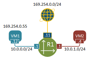
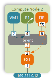
Let’s see what we’re going to be dealing with in this post. This is a simple virtual topology with two VMs sitting in two different subnets. VM1 has a floating IP assigned that is used for external access.
Before we get to the packet walk details, let me briefly describe how to build the above topology using Neutron CLI. I’ll assume that OpenStack has just been installed and nothing has been configured yet, effectively we’ll pick up from where we left our lab in the previous post.
Virtual topology setup
Upload Cirros Linux image to OpenStack’s image repository
curl http://download.cirros-cloud.net/0.3.4/cirros-0.3.4-x86_64-disk.img | glance \
     image-create --name='IMG-CIRROS' \
     --visibility=public \
     --container-format=bare \
     --disk-format=qcow2
Create 2 virtual subnets - RED and BLUE
neutron net-create NET-BLUE
neutron subnet-create --name SUB-BLUE NET-BLUE 10.0.0.0/24 \
  --dns-nameserver 8.8.8.8

neutron net-create NET-RED
neutron subnet-create --name SUB-RED NET-RED 10.0.1.0/24 \
  --dns-nameserver 8.8.8.8
Create external network
neutron net-create EXT-NET --provider:network_type flat \
  --provider:physical_network extnet  \
  --router:external \
  --shared

neutron subnet-create --name EXT-SUB \
 --enable_dhcp=False \
 --allocation-pool=start=169.254.0.50,end=169.254.0.99 \
 --gateway=169.254.0.1 EXT-NET 169.254.0.0/24
Create a router and attach it to all three networks created above
neutron router-create R1
neutron router-interface-add R1 SUB-RED
neutron router-interface-add R1 SUB-BLUE
neutron router-gateway-set R1 EXT-NET
Create two host aggregates to spread the VMs across two different hosts
nova aggregate-create AGG-RED AZ-RED
nova aggregate-create AGG-BLUE AZ-BLUE
nova aggregate-add-host AGG-BLUE compute-2
nova aggregate-add-host AGG-RED compute-3
Boot VMs on two different hypervisors
nova boot --flavor m1.tiny --image 'IMG-CIRROS' \
     --nic net-name=NET-BLUE \
    --availability-zone AZ-BLUE \
     VM1

nova boot --flavor m1.tiny --image 'IMG-CIRROS' \
    --nic net-name=NET-RED \
    --availability-zone AZ-RED \
    VM2
Assign a floating IP (Static NAT) to VM1
nova floating-ip-create EXT-NET
nova floating-ip-associate VM1 169.254.0.55
Enable ingress ICMP and SSH access
nova secgroup-add-rule default tcp 22 22 0.0.0.0/0
nova secgroup-add-rule default icmp -1 -1 0.0.0.0/0
Make sure that both VMs are up and running.
+--------------------------------------+------+--------+------------+-------------+----------------------------------+
| ID                                   | Name | Status | Task State | Power State | Networks                         |
+--------------------------------------+------+--------+------------+-------------+----------------------------------+
| 92263ae8-43d1-4cd0-b271-2b11f0efbe7f | VM1  | ACTIVE | -          | Running     | NET-BLUE=10.0.0.12, 169.254.0.55 |
| b4562f24-2461-49fb-875b-fa1bf869dc4a | VM2  | ACTIVE | -          | Running     | NET-RED=10.0.1.4                 |
+--------------------------------------+------+--------+------------+-------------+----------------------------------+
non-DVR traffic flow
Using the technique described in my earlier post I’ve collected the dynamically allocated port numbers and created a physical representation of our virtual network.
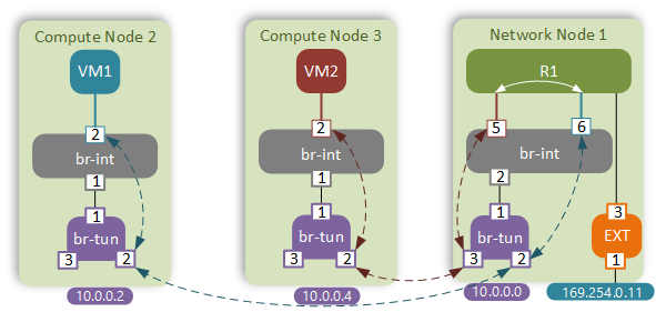
For the sake of brevity I will omit the verification commands. The traffic flow between VM1 and VM2 will follow the standard path that I’ve explored in my native Neutron SDN post.
It is obvious that in this case traffic flows are suboptimal. Instead of going directly between the peer compute nodes, the packet has to hairpin through a Neutron router. This adds to the end-to-end latency and creates unnecessary load on the Network node. These are one of the main reasons why Distributed Virtual Routing was introduced in OpenStack Juno.
Enabling DVR
Enabling DVR requires configuration changes of multiple files on all OpenStack nodes. At a high level, all compute nodes will now run Neutron’s L3-agent service which will be responsible for provisioning of DVR and other auxiliary namespaces. The details of specific configuration options that need to be enabled can be found in the official OpenStack Networking guide. As usual, I’ve incorporated all the necessary changes into a single Chef cookbook, so in order to enable DVR in our lab all what you need to do is run the following commands from the UNetLab VM:
git pull origin master
chef-client -z -E lab neutron.rb
Once all changes has been made, we need to either create a new router or update the existing one to enable the DVR functionality:
neutron router-update --admin-state-up False --distributed True R1
neutron router-update --admin-state-up True R1
DVR East-West traffic flow
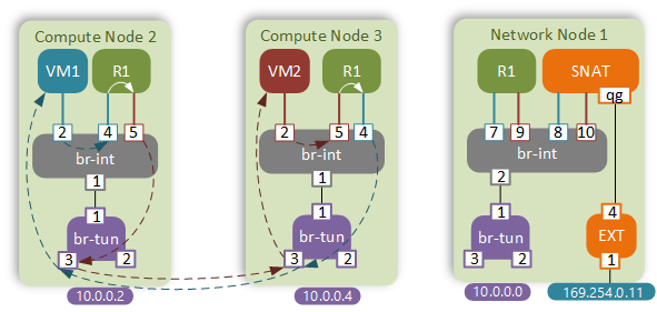
Now let’s see how the traffic flows have changed with the introduction of DVR.
We’re going to be examining the following traffic flow:
- From VM1 (10.0.0.12/fa:16:3e:83:92:96)
- Via router R1 (10.0.0.1/fa:16:3e:72:7a:50; 10.0.1.1/fa:16:3e:6a:2c:8b)
- To VM2 (10.0.1.4/fa:16:3e:76:31:68)
R1 now has an instance on all compute nodes that have VMs in the BLUE or RED networks. That means that VM1 will send a packet directly to the R1’s BLUE interface via the integration bridge.
$ ovs-appctl fdb/show br-int
 port  VLAN  MAC                Age
    2     1  fa:16:3e:83:92:96    1
    4     1  fa:16:3e:72:7a:50    1
    5     2  fa:16:3e:6a:2c:8b    1
This is dynamically populated MAC address table of the integration bridge. You can see that the MAC address of VM1 and both interfaces of R1 have been learned. That means that when VM1 sends a packet to its default gateway’s MAC address, it will go directly to R1’s BLUE interface on port 4.
In this post I will omit the details of ARP resolution process which remains the same as before, however there’s one interesting detail that is worth mentioning before we move on. During the initial flood-and-learn phase on the br-int, the ARP request will get flooded down to the tunnel bridge. As per the standard behaviour, the packet should get replicated to all nodes. However, in this case we don’t want to hear responses from other nodes, since the router is hosted locally. In order to help that, tunnel bridges explicitly drop all packets coming from integration bridges and destined for MAC addresses of locally hosted routers:
$ ovs-appctl ofproto/trace br-tun in_port=1,dl_vlan=1,dl_dst=fa:16:3e:72:7a:50 | grep -E "Rule|action"
Rule: table=0 cookie=0xa3536ac94478bd1d priority=1,in_port=1
OpenFlow actions=goto_table:1
        Rule: table=1 cookie=0xa3536ac94478bd1d priority=2,dl_vlan=1,dl_dst=fa:16:3e:72:7a:50
        OpenFlow actions=drop
Getting back to our traffic flow, once the IP packet has reached the DVR instance of R1 on compute node #2, the routing lookup occurs and the packet is sent back to the integration bridge with a new source MAC of R1’s RED interface.
$ ip netns exec qrouter-uuid ip route
10.0.0.0/24 dev qr-102c4426-86  proto kernel  scope link  src 10.0.0.1
10.0.1.0/24 dev qr-3779302e-62  proto kernel  scope link  src 10.0.1.1
Tunnel bridge will do its usual work by locating the target compute node based on the destination MAC address of VM2 (DVR requires L2 population to be enabled) and will send the packet directly to the compute node #3.
$ ovs-appctl ofproto/trace br-tun in_port=1,dl_vlan=2,dl_src=fa:16:3e:6a:2c:8b,dl_dst=fa:16:3e:76:31:68 | grep -E "Rule|action"
Rule: table=0 cookie=0xa3536ac94478bd1d priority=1,in_port=1
OpenFlow actions=goto_table:1
        Rule: table=1 cookie=0xa3536ac94478bd1d priority=1,dl_vlan=2,dl_src=fa:16:3e:6a:2c:8b
        OpenFlow actions=set_field:fa:16:3f:d3:10:60->eth_src,goto_table:2
                Rule: table=2 cookie=0xa3536ac94478bd1d priority=0,dl_dst=00:00:00:00:00:00/01:00:00:00:00:00
                OpenFlow actions=goto_table:20
                        Rule: table=20 cookie=0xa3536ac94478bd1d priority=2,dl_vlan=2,dl_dst=fa:16:3e:76:31:68
                        OpenFlow actions=pop_vlan,set_field:0x4d->tun_id,output:3
Since all instances of R1 have the same set of IP/MAC addresses, the MAC address of a local router can be learned by the remote integration bridge hosting the same instance of DVR. In order to prevent that from happening, the sending br-tun replaces the source MAC address of the frame with the set_field:fa:16:3f:d3:10:60->eth_src action. This way the real R1’s MAC address gets masked as the frame leaves the node. These “mask” MACs are generated by and learned from the Neutron server, which ensures that each node gets a unique address.
The receiving node’s br-tun will swap the VXLAN header with a VLAN ID and forward the frame up to the integration bridge.
$ ovs-appctl ofproto/trace br-tun in_port=3,tun_id=0x4d,dl_dst=fa:16:3e:76:31:68 | grep -E "Rule|action"
Rule: table=0 cookie=0x8a7dedf35101427f priority=1,in_port=3
OpenFlow actions=goto_table:4
        Rule: table=4 cookie=0x8a7dedf35101427f priority=1,tun_id=0x4d
        OpenFlow actions=push_vlan:0x8100,set_field:4097->vlan_vid,goto_table:9
                Rule: table=9 cookie=0x8a7dedf35101427f priority=0
                OpenFlow actions=goto_table:10
                        Rule: table=10 cookie=0x8a7dedf35101427f priority=1
                        OpenFlow actions=learn(table=20,hard_timeout=300,priority=1,cookie=0x8a7dedf35101427f,NXM_OF_VLAN_TCI[0..11],NXM_OF_ETH_DST[]=NXM_OF_ETH_SRC[],load:0->NXM_OF_VLAN_TCI[],load:NXM_NX_TUN_ID[]->NXM_NX_TUN_ID[],output:OXM_OF_IN_PORT[]),output:1
                                Rule: table=0 cookie=0x9a1e0026794eadc5 priority=1
                                OpenFlow actions=NORMAL
Integration bridge of compute node #3 will lookup the destination MAC address and send the packet out port 2.
$ ovs-appctl fdb/show br-int
 port  VLAN  MAC                Age
    2     1  fa:16:3e:76:31:68    0
    4     2  fa:16:3e:72:7a:50    0
    5     1  fa:16:3e:6a:2c:8b    0
    1     1  fa:16:3e:29:de:20    0
The reverse packet flow is similar - the packet will get routed on the compute node #3 and sent in a BLUE network to the compute node #2.
External connectivity
External connectivity will be very different for VMs with and without a floating IP. We will examine each case individually.
Case 1 - Overload NAT (VM2 with no FIP)
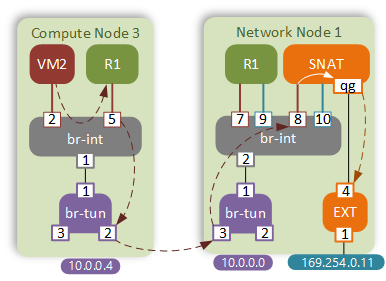
External connectivity for VMs with no floating IP is still performed by the Network node. This time however, NATing is performed by a new element - SNAT namespace. As per the normal behaviour, VM2 will send a packet to its default gateway first. Let’s have a closer look at the routing table of the DVR:
$ ip netns exec qrouter-uuid ip route
10.0.0.0/24 dev qr-102c4426-86  proto kernel  scope link  src 10.0.0.1
10.0.1.0/24 dev qr-3779302e-62  proto kernel  scope link  src 10.0.1.1
There’s no default route in the main routing table, so how would it get routed out? DVRs extensively use Linux routing policy database (RPDB), a feature that has a lot in common with OpenFlow tables. The principle of RPDB is that every packet gets matched against a set of routing tables until there’s a hit. The tables are checked in the order of their priority (lowest to highest). One of the main features of RPDB is the ability to perform matches based on something other than the destination IP address, which is why it’s often referred to as policy-based routing. To view the contents of RPDB use the ip rule command under the DVR namespace:
$ ip netns exec qrouter-uuid ip rule
0:      from all lookup local
32766:  from all lookup main
32767:  from all lookup default
167772161:      from 10.0.0.1/24 lookup 167772161
167772417:      from 10.0.1.1/24 lookup 167772417
In our case table 167772161 matches all packets sourced from the BLUE subnet and if we examine the corresponding routing table we’ll find the missing default route there.
$ ip netns exec qrouter-uuid ip route list table 167772417
default via 10.0.1.12 dev qr-3779302e-62
The next hop of this default route points to the SNAT’s interface in the BLUE network. MAC address is statically programmed by the local L3-agent.
$ ip netns exec qrouter-uuid ip neigh | grep 10.0.1.12
10.0.1.12 dev qr-3779302e-62 lladdr fa:16:3e:29:de:20 PERMANENT
Integration bridge sends the packet out port 1 to the tunnel bridge.
$ ovs-appctl fdb/show br-int | grep fa:16:3e:29:de:20
    1     1  fa:16:3e:29:de:20    1
Tunnel bridge finds the corresponding match and sends the VXLAN-encapsulated packet to the Network node.
$ ovs-appctl ofproto/trace br-tun in_port=1,dl_vlan=1,dl_dst=fa:16:3e:29:de:20 | tail -n 1
Datapath actions: set(tunnel(tun_id=0x4d,src=10.0.0.4,dst=10.0.0.0,ttl=64,flags(df|key))),pop_vlan,3
Tunnel bridge of the Network node forwards the frame up to the integration bridge.
$ ovs-appctl ofproto/trace br-tun in_port=3,tun_id=0x4d,dl_dst=fa:16:3e:29:de:20 | grep output
OpenFlow actions=learn(table=20,hard_timeout=300,priority=1,cookie=0xb9be3fe62922c800,NXM_OF_VLAN_TCI[0..11],NXM_OF_ETH_DST[]=NXM_OF_ETH_SRC[],load:0->NXM_OF_VLAN_TCI[],load:NXM_NX_TUN_ID[]->NXM_NX_TUN_ID[],output:OXM_OF_IN_PORT[]),output:1
Integration bridge sends the frame to port 10, which is where SNAT namespace is attached
$ ovs-appctl fdb/show br-int | grep fa:16:3e:29:de:20
   10     1  fa:16:3e:29:de:20    0
SNAT is a namespace with an interface in each of the subnets - BLUE, RED and External subnet
$ ip netns exec snat-uuid ip a | grep -E "UP|inet"
16: sg-fefd493b-a5: <BROADCAST,MULTICAST,UP,LOWER_UP> mtu 1450 qdisc noqueue state UNKNOWN
    link/ether fa:16:3e:99:5c:3a brd ff:ff:ff:ff:ff:ff
    inet 10.0.0.6/24 brd 10.0.0.255 scope global sg-fefd493b-a5
18: sg-b3d58360-b4: <BROADCAST,MULTICAST,UP,LOWER_UP> mtu 1450 qdisc noqueue state UNKNOWN
    link/ether fa:16:3e:29:de:20 brd ff:ff:ff:ff:ff:ff
    inet 10.0.1.12/24 brd 10.0.1.255 scope global sg-b3d58360-b4
19: qg-765b5aca-ce: <BROADCAST,MULTICAST,UP,LOWER_UP> mtu 1500 qdisc noqueue state UNKNOWN
    link/ether fa:16:3e:d5:75:0e brd ff:ff:ff:ff:ff:ff
    inet 169.254.0.57/24 brd 169.254.0.255 scope global qg-765b5aca-ce
SNAT has a single default route pointing to the External network’s gateway.
$ ip netns exec snat-uuid ip route | grep default
default via 169.254.0.1 dev qg-765b5aca-ce
Before sending the packet out, iptables will NAT the packet to hide it behind SNAT’s qg external interface IP.
$ ip netns exec snat-uuid iptables -t nat -L | grep SNAT
SNAT       all  --  anywhere             anywhere             to:169.254.0.57
Case 2 - Static NAT (VM1 with FIP)
The first step in this scenario is the same - VM1 sends a packet to the MAC address of its default gateway. As before, the default route is missing in the main routing table.
$ ip netns exec qrouter-uuid ip route list table main
10.0.0.0/24 dev qr-102c4426-86  proto kernel  scope link  src 10.0.0.1
10.0.1.0/24 dev qr-3779302e-62  proto kernel  scope link  src 10.0.1.1
169.254.106.114/31 dev rfp-e4d4897e-7  proto kernel  scope link  src 169.254.106.114
Looking at the ip rule configuration we can find that table 16 matches all packets from that particular VM (10.0.0.12).
$ ip netns exec qrouter-uuid ip rule
0:      from all lookup local
32766:  from all lookup main
32767:  from all lookup default
57481:  from 10.0.0.12 lookup 16
167772161:      from 10.0.0.1/24 lookup 167772161
167772417:      from 10.0.1.1/24 lookup 167772417
Routing table 16 sends the packet via a point-to-point veth pair link to the FIP namespace.
$ ip netns exec qrouter-uuid ip route list table 16
default via 169.254.106.115 dev rfp-e4d4897e-7
Before sending the packet out, DVR translates the source IP of the packet to the FIP assigned to that VM.
$ ip netns exec qrouter-uuid iptables -t nat -L | grep NAT
SNAT       all  --  10.0.0.12            anywhere             to:169.254.0.55
A FIP namespace is a simple router designed to connect multiple DVRs to external network. This way all routers can share the same “uplink” namespace and don’t have to consume valuable addresses from external subnet.
$ ip netns exec fip-uuid ip a | grep -E "UP|inet"
2: fpr-e4d4897e-7: <BROADCAST,MULTICAST,UP,LOWER_UP> mtu 1500 qdisc pfifo_fast state UP qlen 1000
    inet 169.254.106.115/31 scope global fpr-e4d4897e-7
15: fg-d3bb699d-af: <BROADCAST,MULTICAST,UP,LOWER_UP> mtu 1500 qdisc noqueue state UNKNOWN
    inet 169.254.0.58/24 brd 169.254.0.255 scope global fg-d3bb699d-af
Default route inside the FIP namespace points to the External subnet’s gateway IP.
$ ip netns exec fip-uuid ip route | grep default
default via 169.254.0.1 dev fg-d3bb699d-af
The MAC address of the gateway is statically configured by the L3 agent.
$ ip netns exec fip-uuid ip neigh | grep 169.254.0.1
169.254.0.1 dev fg-d3bb699d-af lladdr 32:3e:7d:13:ca:78 DELAY
The packet is sent to the br-int with the destination MAC address of the default gateway, which is learned on port 3.
$ ovs-appctl fdb/show br-int | grep 32:3e:7d:13:ca:78
  3     3  32:3e:7d:13:ca:78    1
External bridge strips the VLAN ID of the packet coming from the br-int and does the lookup in the dynamic MAC address table.
$ ovs-appctl ofproto/trace br-ex in_port=2,dl_vlan=3 | grep actions=
OpenFlow actions=pop_vlan,NORMAL
The frame is forwarded out the physical interface.
$ ovs-appctl fdb/show br-ex | grep 32:3e:7d:13:ca:78
1     0  32:3e:7d:13:ca:78    1
Reverse packet flow will be quite similar, however in this case FIP namespace must be able to respond to ARP requests for the IPs that only exist on DVRs. In order to do that, it uses a proxy-ARP feature. First, L3 agent installs a static route for the FIP pointing back to the correct DVR over the veth pair interface:
$ ip netns exec fip-uuid ip route get 169.254.0.55
169.254.0.55 via 169.254.106.114 dev fpr-e4d4897e-7  src 169.254.106.115
Now that the FIP namespace knows the route to the floating IP, it can respond to ARPs on behalf of DVR as long as proxy-ARP is enabled on the external fg interface:
$ ip netns exec fip-uuid
cat /proc/sys/net/ipv4/conf/fg-d3bb699d-af/proxy_arp
1
Finally, the DVR NATs the packet back to its internal IP in the BLUE subnet and forwards it straight to VM1.
$ ip netns exec qrouter-uuid iptables -t nat -L | grep DNAT
DNAT       all  --  anywhere             169.254.0.55         to:10.0.0.12
DVR Pros and Cons
Without a doubt DVR has introduced a number of much needed improvements to OpenStack networking:
- East-West traffic now follows the most optimal path thereby reducing the load on the Network node.
- External connectivity to floating IPs now also follows the most optimal path directly to the compute node hosting the VM.
However, there’s a number of issues that either remain unaddressed or result directly from the current DVR architecture:
- DHCP and SNAT are still hosted on the Network node.
- Asymmetric routing means that every DVR needs to have an interface in every configured subnet, even when there are no VMs that belong to those subnets on the current compute node.
- Direct connectivity to FIP means that all compute nodes now need to have direct L2 adjacency to external subnets.
- FIP namespace on compute nodes consumes IP addresses from external subnets which can be a problem if external subnet is in a public IPv4 address range.
- DVR implementation as a network namespace creates additional overhead in packet processing.
Some of the above issues are not critical and can be fixed with a little effort:
- In order to reduce the scope of a External network VLAN span inside the DC, dedicate a subset of hosts that will have a direct L2 adjacency to external networks and only deploy external-facing VMs on those hosts.
- Since FIP namespace only requires an external IP address for debugging purposes, we can create an additional, secondary, subnet in RFC1918 space for FIP connectivity. This is enabled by a feature called subnet “Service types” and is available in the latest Newton release.
However the main issue still remains unresolved. Every North-South packet has to hop several times between the global and DVR/FIP/NAT namespaces. These kind of operations are very expensive in terms of consumed CPU and memory resources and can be very detrimental to network performance. Using namespaces may be the most straight-forward and non-disruptive way of implementing DVR, however it’s definitely not the most optimal. Ideally we’d like to see both L2 and L3 pipelines implemented in OpenvSwitch tables. This way all packets can benefit from OVS fast-path flow caching. But fear not, the solution to this already exists in a shape of Open Virtual Network. OVN is a project spawned from the OVS and aims to address a number of shortcomings existing in current implementations of virtual networks.