News about UnetLab
Those who read my blog regularly know that I’m a big fan of a network simulator called UnetLab. For the last two years I’ve done all my labbing in UNL and was constantly surprised by how extensible and stable it has been. I believe that projects like this are very important to our networking community because they help train the new generation of network engineers and enable them to expand their horizons. Recently UnetLab team has decided take the next step and create a new version of UNL. This new project, called EVE-NG, will help users build labs of any size and run full replicas of their production networks, which is ideal for pre-deployment testing of network changes. If you want to learn more, check out the EVE-NG page on indiegogo.
Creating vQFX nodes in UnetLab
Back to the business at hand, vQFX is not publically available yet but is expected to pop up at Juniper.net some time in the future. Similar to a recently released vMX, vQFX will consist of two virtual machines - one running the routing engine (RE) and second simulating the ASIC forwarding piplines (PFE). You can find more information about these images on Juniper’s Github page. Images get distributed in multiple formats but in the context of this post we’ll only deal with two VMDK files:
vqfx10k-re-15.1X53-D60.vmdk
vqfx10k-pfe-20160609-2.vmdk
To be able to use these images in UnetLab, we first need to convert them to qcow2 format and copy them to the directory where UNL stores all its qemu images:
 mkdir /opt/unetlab/addons/qemu/qfx_re-15d1X53
 mkdir /opt/unetlab/addons/qemu/qfx_pfe-20160609

/opt/qemu/bin/qemu-img convert -f vmdk -O qcow2 vqfx10k-pfe-20160609-2.vmdk /opt/unetlab/addons/qemu/qfx_pfe-20160609/hda.qcow2

/opt/qemu/bin/qemu-img convert -f vmdk -O qcow2 vqfx10k-re-15.1X53-D60.vmdk /opt/unetlab/addons/qemu/qfx_re-15d1X53/hda.qcow2
Next, we need to create new node definitions for RE and PFE VMs. The easiest way would be to clone the linux node type:
cd /opt/unetlab/html/templates
cp linux.php qfx_pfe.php
cp linux.php qfx_re.php

sed -i 's/2048/1024/; s/virtio-net-pci/e1000/; s/Server/Switch/' qfx_re.php
sed -i 's/2048/1536/; s/virtio-net-pci/e1000/; s/Server/Switch/' qfx_pfe.php

sed -i 's/Linux/QFX_RE/g; s/linux/qfx_re/g' qfx_re.php
sed -i 's/Linux/QFX_PFE/g; s/linux/qfx_pfe/g' qfx_pfe.php

sed -ri 's/(.*ethernet.*) = 1/\1 = 2/' qfx_pfe.php
sed -ri 's/(.*ethernet.*) = 1/\1 = 8/' qfx_re.php
Now let’s add the QFX to the list of nodes by modifying the following file:
$ cat /opt/unetlab/html/includes/init.php
'openstack'             =>      'OpenStack',
'qfx_re'                =>      'QFX10k-RE',
'qfx_pfe'               =>      'QFX10k-PFE',
'mikrotik'              =>      'MikroTik RouterOS',
Optionally, /opt/unetlab/html/includes/__node.php can be modified to change the default naming convention similar to the vmx node.
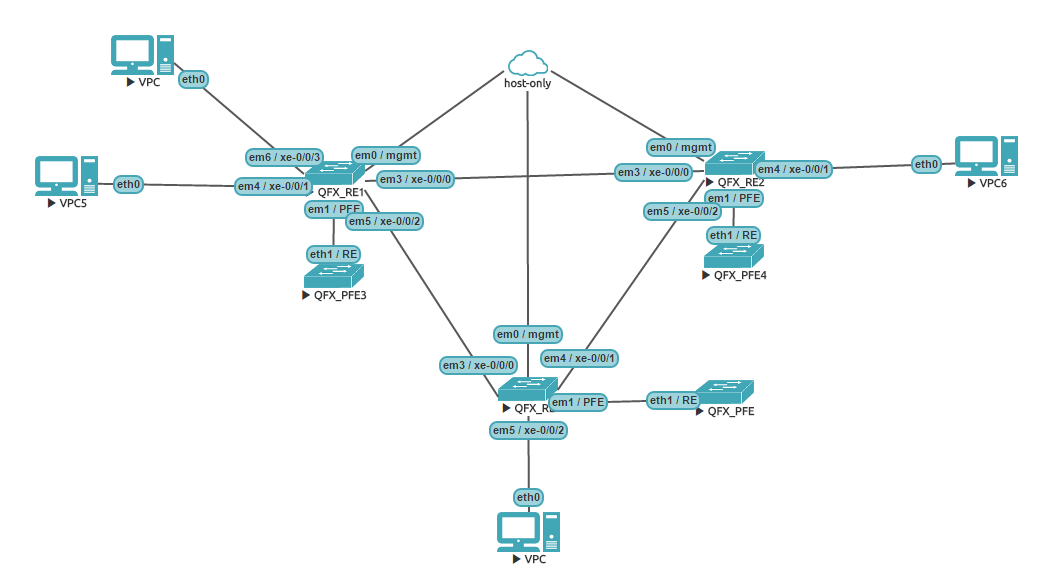
Once you’ve done all the above changes, you should have a working vQFX 10k node available in UNL GUI. For the purpose of demonstration of EVPN features I’ve created the following topology:
EVPN L2 and L3 services
EVPN standards define multiple routes types to distribute NLRI information across the network. The two most “significant” route types are 2 and 5. Type-2 NLRI was designed to carry the MAC (and optionally IP) address to VTEP IP binding information which is used to populate the dynamic MAC address table. This function, that was previously accomplished by a central SDN controller, is now performed in a scalable, standard-based, controller-independent fashion. Type-5 NLRI contains IP Prefix to VTEP IP mapping and is similar to the function of traditional L3 VPNs. In order to explore the capabilities of EVPN implementation on vQFX I’ve created and artificial scenario with 3 virtual switches, 3 VLANs and 4 hosts.
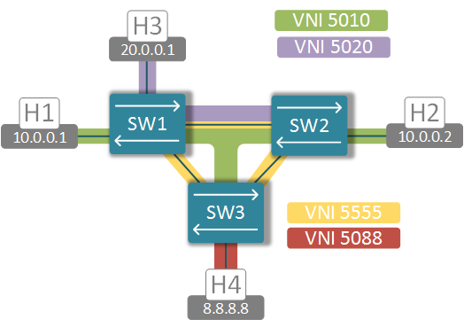
VLAN10 (green) is present on all 3 switches, VLAN20 (purple) is only configured on switches 1 and 2 and VLAN88 (red) only exists on SW3. I’ve provided configuration snippets below for reference purposes only and only for SW1. Remaining switches are configured similarly.
Configuring Basic IP and BGP setup
set interfaces xe-0/0/0 unit 0 family inet address 12.12.12.1/24
set interfaces xe-0/0/2 unit 0 family inet address 13.13.13.1/24
set interfaces lo0 unit 0 family inet address 99.99.99.1/32
set routing-options static route 99.99.99.2/32 next-hop 12.12.12.2
set routing-options static route 99.99.99.3/32 next-hop 13.13.13.3

set routing-options router-id 99.99.99.1
set routing-options autonomous-system 555

set routing-options autonomous-system 555
set protocols bgp group EVPN type internal
set protocols bgp group EVPN local-address 99.99.99.1
set protocols bgp group EVPN family evpn signaling
set protocols bgp group EVPN neighbor 99.99.99.2
set protocols bgp group EVPN neighbor 99.99.99.3
Configuring End-host connectivity and IRB
set vlans BD5010 vlan-id 10
set vlans BD5010 l3-interface irb.10
set vlans BD5020 vlan-id 20
set vlans BD5020 l3-interface irb.20
set interfaces xe-0/0/1 unit 0 family ethernet-switching vlan members 10
set interfaces xe-0/0/3 unit 0 family ethernet-switching vlan members 20
set interfaces irb unit 10 family inet address 10.0.0.254/24
set interfaces irb unit 20 family inet address 20.0.0.254/24
Configuring L2 EVPN services
set protocols evpn encapsulation vxlan
set protocols evpn extended-vni-list all
set protocols evpn multicast-mode ingress-replication

set switch-options vtep-source-interface lo0.0
set switch-options route-distinguisher 555:0
set switch-options vrf-target target:555:123

set vlans BD5010 vxlan vni 5010
set vlans BD5010 vxlan ingress-node-replication
set vlans BD5020 vxlan vni 5020
set vlans BD5020 vxlan ingress-node-replication
Configuring L3 EVPN service
set routing-instances EVPN-VRF instance-type vrf
set routing-instances EVPN-VRF interface irb.10
set routing-instances EVPN-VRF interface irb.20
set routing-instances EVPN-VRF interface lo0.10
set routing-instances EVPN-VRF route-distinguisher 555:1
set routing-instances EVPN-VRF vrf-target target:123:5055
set routing-instances EVPN-VRF protocols evpn ip-prefix-routes advertise direct-nexthop
set routing-instances EVPN-VRF protocols evpn ip-prefix-routes encapsulation vxlan
set routing-instances EVPN-VRF protocols evpn ip-prefix-routes vni 5555
Traffic flow overview
Once all the nodes have been configured, we can have a closer look at the traffic flows, specifically at how packets are being forwarded and where the L2 and L3 lookups take place.
L2 forwarding - H1 to H2 (00:50:79:66:68:06)
Traffic from H1 to H2 will never leave its own broadcast domain. As soon as the packet hits the incoming interface of SW1, MAC address lookup occurs pointing to the remote VTEP interface of SW2.
SW1> show ethernet-switching table | match 00:50:79:66:68:06
   BD5010              00:50:79:66:68:06   D        vtep.32769             99.99.99.2
Once SW2 decapsulates the packet, the lookup in the MAC address table returns the locally connected interface, where it gets forwarded next.
SW2> show ethernet-switching table | match 00:50:79:66:68:06
   BD5010              00:50:79:66:68:06   D        xe-0/0/1.0
L3 forwarding (symmetric) - H3 to H4
The route to 8.8.8.0/24 is advertised by SW3 in type-5 NLRI
SW1> show route receive-protocol bgp 99.99.99.3 extensive
* 5:555:1::0::8.8.8.0::24/304 (1 entry, 1 announced)
     Import Accepted
     Route Distinguisher: 555:1
     Route Label: 5555
     Overlay gateway address: 0.0.0.0
     Nexthop: 99.99.99.3
     Localpref: 100
     AS path: I
     Communities: target:123:5055 encapsulation0:0:0:0:vxlan router-mac:02:05:86:71:72:00
This NLRI doesn’t contain any overlay gateway address, however it does have a special “router-mac” community with a globally unique SW3’s chassis MAC. This MAC is advertised as normal type-2 MAC address and points to the remote VTEP interface of SW3:
SW1> show ethernet-switching table | match 02:05:86:71:72:00
   BD5010              02:05:86:71:72:00   D        vtep.32770             99.99.99.3
The above two pieces of information are fed into our EVPN-VRF routing table to produce the entry with the following parameters:
SW1> show route table EVPN-VRF.inet.0 detail 8.8.8.8 | match "VTEP|VNI|MAC"
Encap VNI: 5555, Decap VNI: 5555
Source VTEP: 99.99.99.1, Destination VTEP: 99.99.99.3
SMAC: 02:05:86:71:3b:00, DMAC: 02:05:86:71:72:00
This is the example of how “symmetric” IRB routing is performed. Instead of routing the packet at the ingress and switching at the egress node, how it was done in the case of Neutron’s DVR, the routing is performed twice. First the packet is routed into a “transit” VNI 5555, which glues all the switches in the same EVI together from the L3 perspective. Once the packet reaches the destination node, it gets routed into the intended VNI (5088 in our case) and forwarded out the local interface. This way switches may have different sets of VLANs and IRBs and still be able route packets between VXLANs.
L3 forwarding (asymmetric) - H1 to H4
As you may have noticed, the green broadcast domain extends to all three switches, even though hosts are only attached to the first two. Let’s see how it will affect the packet flows. The flow from H1 to H4 will be similar to the one from H3 to H4 described above. However return packets will get routed on SW3 directly into VXLAN5010, since that switch has an IRB.10 interface and then switched all the way to H1.
SW3> show route forwarding-table destination 10.0.0.1
Routing table: EVPN-VRF.inet
Internet:
Destination        Type RtRef Next hop           Type Index    NhRef Netif
10.0.0.1/32        dest     0 0:50:79:66:68:5    ucst     1772     1 vtep.32770
This is the example of “asymmetric” routing, similar to the one exhibited by Neutron DVR. You would see similar behaviour if you examined the flow between H3 and H2.
Conclusion
So why all the hassle configuring EPVN on data centre switches? For one, you can get rid of MLAG in TOR switches and replace it with EVPN multihoming. However, the main benefit is that you can stretch L2 broadcast domains across your whole data centre without the need for an SDN controller. So, for example, we can now easily satisfy the requirement of having external floating IP network on all compute nodes introduced by Neutron DVR. EVPN-enabled switches can also now perform functions similar to DC gateway routers (the likes of ASR, MX or SR) while giving you the benefits of horizontal scaling of Leaf/Spine networks. As more and more vendors introduce EVPN support, it is poised to become the ultimate DC routing protocol, complementing the functions already performed by the host-based virtual switches, and with all the DC switches running BGP already, introducing EVPN may be as easy as enabling a new address family.